Resistor Color Code Chart: How to Read 4, 5, and 6 Band Resistors
A 4.7 kΩ carbon-composition resistor labeled yellow-violet-red-gold was the workhorse of every hobby electronics kit from the late 1930s onward, and the color ordering was not chosen by wavelength or alphabet. It was chosen because those specific pigments survived the 800 °C curing oven used to bake resistive film onto a ceramic core without shifting hue. Black carbon, brown iron oxide, red iron oxide, and the rest of the palette were already stable pigments in the ceramic industry. Whoever picked the code at the Radio Manufacturers Association in the 1920s was solving a materials-science problem first and a readability problem second.
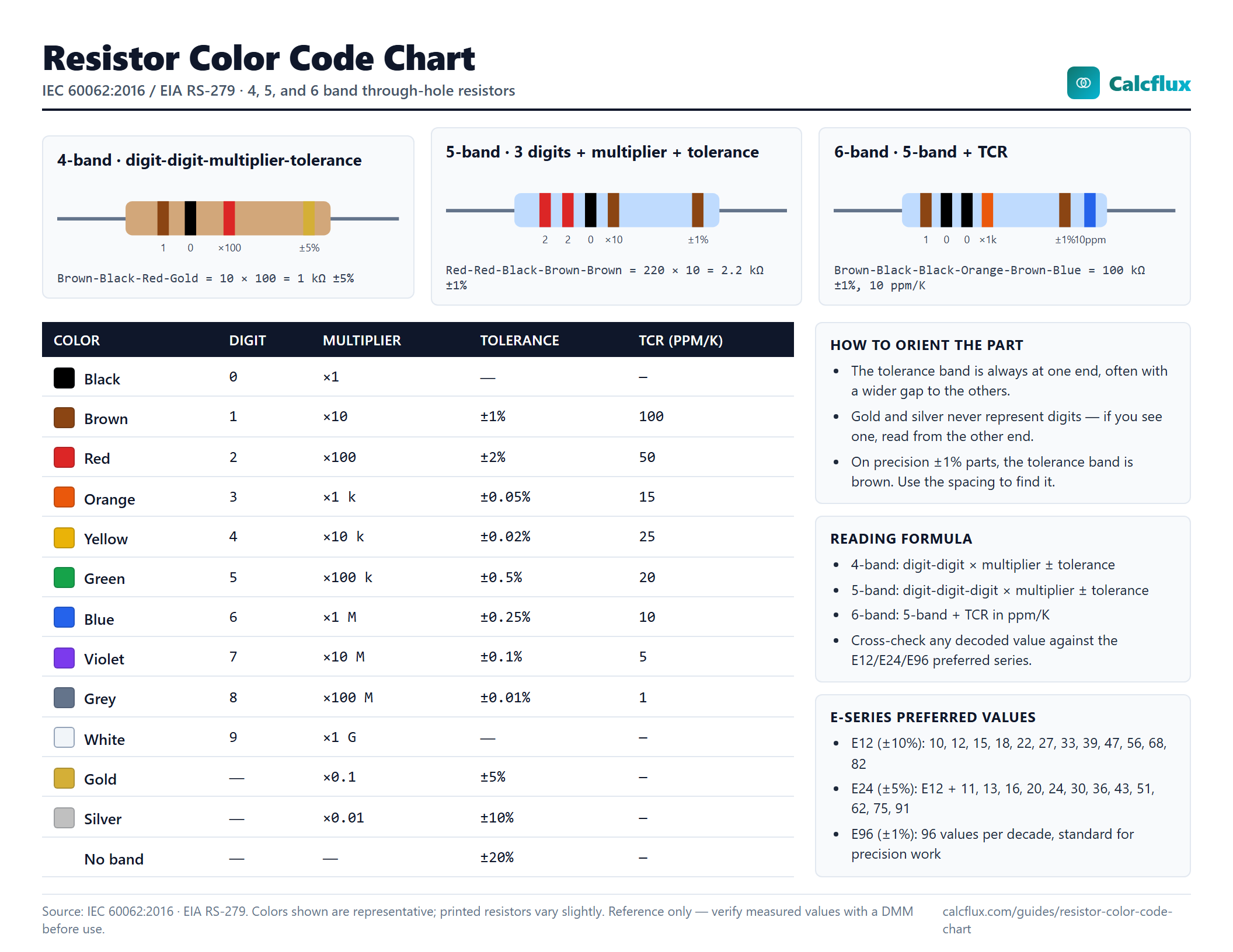
The code that came out of that constraint has barely changed in ninety years. It is codified today as IEC 60062 internationally and EIA RS-279 in the United States, it reads left to right on every modern through-hole resistor, and once you know the ten colors plus gold and silver you can read any 4, 5, or 6 band part on the bench without a meter.
Printable reference. Grab the color code poster (PNG, letter size) for your workbench. All 12 colors, 4/5/6-band layouts, reading rules, and E-series values on one sheet.
The Color Code Table
Every band on a resistor does one of four jobs: digit, multiplier, tolerance, or temperature coefficient. The same color can mean different things depending on position. This is the master table, using IEC 60062:2016 values.
| Color | Digit | Multiplier | Tolerance | TCR (ppm/K) |
|---|---|---|---|---|
| Black | 0 | ×1 | n/a | n/a |
| Brown | 1 | ×10 | ±1% | 100 |
| Red | 2 | ×100 | ±2% | 50 |
| Orange | 3 | ×1,000 | ±0.05% | 15 |
| Yellow | 4 | ×10,000 | ±0.02% | 25 |
| Green | 5 | ×100,000 | ±0.5% | 20 |
| Blue | 6 | ×1,000,000 | ±0.25% | 10 |
| Violet | 7 | ×10,000,000 | ±0.1% | 5 |
| Grey | 8 | ×100,000,000 | ±0.01% | 1 |
| White | 9 | ×1,000,000,000 | n/a | n/a |
| Gold | n/a | ×0.1 | ±5% | n/a |
| Silver | n/a | ×0.01 | ±10% | n/a |
| (none) | n/a | n/a | ±20% | n/a |
Gold and silver appear only as multipliers (for sub-ohm values) or tolerance bands. They never represent digits. That single fact is half the battle when you are trying to figure out which end of the resistor to read first.
Reading 4-Band Resistors
A 4-band resistor uses the simplest layout: two digit bands, one multiplier, one tolerance. The tolerance band is always gold, silver, or a wider-spaced band; the side with the tolerance is the right side when you read the resistor.
Worked example. A resistor shows Brown-Black-Red-Gold. Read left to right:
- Band 1 (Brown) = 1
- Band 2 (Black) = 0
- Band 3 (Red) = ×100
- Band 4 (Gold) = ±5%
Value = 10 × 100 = 1,000 Ω = 1 kΩ ±5%.
Another. Yellow-Violet-Orange-Gold = 47 × 1,000 = 47,000 Ω = 47 kΩ ±5%. Red-Red-Brown-Gold = 22 × 10 = 220 Ω ±5%. Green-Blue-Black-Gold = 56 × 1 = 56 Ω ±5%. The arithmetic is always the same: stick the two digits together, multiply by the third band.
For sub-ohm resistors the multiplier band turns gold or silver. Brown-Black-Gold-Gold = 10 × 0.1 = 1 Ω ±5%. Red-Violet-Silver-Gold = 27 × 0.01 = 0.27 Ω ±5%, the kind you see on current-sense lines inside switching regulators.
The common pitfall with 4-band parts is reading them backwards. If you see Gold-Red-Black-Brown and try to read gold as digit 1, you are upside down. Flip the resistor. The tolerance band (gold, silver, or on precision 4-bands, brown or red) is always last. On most carbon-film parts the tolerance band is also spaced slightly farther from the other three, which is a useful visual cue when the colors are ambiguous. When the space is not obvious, the rule is: gold or silver is never a first band, so if you see one, it is the tolerance band and you read from the other end. Plug the value straight into the resistor color code calculator if you want a sanity check before you solder.
Reading 5-Band Resistors
5-band resistors carry three digit bands instead of two, giving an extra significant figure. They show up wherever ±1% or tighter tolerance matters: instrumentation, precision dividers, feedback networks in op-amp circuits. Layout is digit-digit-digit-multiplier-tolerance.
Worked example. Red-Red-Black-Brown-Brown:
- Band 1 (Red) = 2
- Band 2 (Red) = 2
- Band 3 (Black) = 0
- Band 4 (Brown) = ×10
- Band 5 (Brown) = ±1%
Value = 220 × 10 = 2,200 Ω = 2.2 kΩ ±1%.
Another. Brown-Black-Black-Orange-Brown = 100 × 1,000 = 100,000 Ω = 100 kΩ ±1%. Yellow-Violet-Black-Red-Brown = 470 × 100 = 47 kΩ ±1%. Blue-Grey-Black-Black-Brown = 680 × 1 = 680 Ω ±1%.
5-band parts expose a trap: some resistors printed on light blue or light green bodies have a fifth band that looks ambiguous. If band 5 is brown (±1%) and band 1 is also brown, you can read the part correctly only if you identify the tolerance-band gap or know the part number. When in doubt, measure with a DMM and work backwards from the measured resistance to the likely nominal value using the E-series table below. If your measurement is 2,198 Ω, the nominal is almost certainly 2.2 kΩ from the E24 series, not some 2,198 Ω oddity.
For building and verifying series or parallel combinations of these precision parts, the resistor network calculator handles the arithmetic.
Reading 6-Band Resistors
A 6-band resistor adds one more band after the tolerance: the temperature coefficient of resistance, or TCR, in parts per million per kelvin. This band tells you how much the resistance will drift when the part heats up. A 10 kΩ resistor with 100 ppm/K TCR will shift about 10 Ω for every 10 °C change in temperature. A 10 ppm/K part will shift only 1 Ω for the same rise. For a precision voltage reference, a current-sense in an instrumentation amplifier, or a gain-setting resistor in a temperature-stable oscillator, that difference is the whole point of the design.
TCR band colors, per IEC 60062:2016:
- Brown = 100 ppm/K
- Red = 50 ppm/K
- Orange = 15 ppm/K
- Yellow = 25 ppm/K
- Green = 20 ppm/K
- Blue = 10 ppm/K
- Violet = 5 ppm/K
- Grey = 1 ppm/K
Worked example. Brown-Black-Black-Red-Brown-Red: 100 × 100 = 10 kΩ ±1% with 50 ppm/K. Red-Red-Black-Black-Brown-Blue: 220 × 1 = 220 Ω ±1% with 10 ppm/K TCR, typical of a precision metal-film sense resistor.
6-band parts are far less common than 4- or 5-band; you find them on precision audio gear, lab instrumentation, and reference designs where the designer wants to guarantee thermal behavior at the component level rather than trim it out at calibration. If you cannot see a sixth band, you probably have a 5-band part, not a 6-band with a faded TCR. Faded bands are rare because the IEC specifies light-fast pigments; dirty bands are more common and usually rinse off with isopropyl alcohol.
SMD Resistor Codes
Surface-mount resistors are too small for color bands, so they use printed numeric codes instead. Three conventions dominate.
Three-digit code. The first two digits are significant figures, the third is the power of ten. 103 means 10 × 10³ = 10 kΩ. 472 means 47 × 10² = 4,700 Ω = 4.7 kΩ. 220 means 22 × 10⁰ = 22 Ω (not 220 Ω, a common misread). For sub-ohm values an R marks the decimal point: 4R7 = 4.7 Ω, R22 = 0.22 Ω.
Four-digit code. Used on 1% precision SMDs. First three digits are significant figures, fourth is the power of ten. 1002 = 100 × 10² = 10 kΩ. 4700 = 470 × 10⁰ = 470 Ω. This trips up anyone used to the three-digit convention, because 4700 is 470 Ω, not 4.7 kΩ. The R decimal-point convention still applies: 10R0 = 10.0 Ω.
EIA-96. For 1% resistors in packages too small for four digits (0402, 0603). A two-digit code indexes into a standardized 96-value table (the E96 series), and a single letter encodes the multiplier. The letters: Z = ×0.001, Y = ×0.01, X or S = ×0.1, A = ×1, B or H = ×10, C = ×100, D = ×1,000, E = ×10,000, F = ×100,000. So 01A = 100 Ω, 68C = 499 × 100 = 49.9 kΩ, 01Y = 1.00 Ω. The index-to-value mapping is exactly the E96 series scaled into the range 100 through 976.
Because SMD conventions differ by manufacturer and package size, always cross-check with the part's datasheet when the value matters. A cheap DMM clears most ambiguity in about two seconds.
E-Series Preferred Values
You cannot stock every possible resistance value, and you do not need to. Carbon-film and metal-film resistors are manufactured in batches and then sorted by measured value into tolerance bins, so the production line naturally produces a log-spaced distribution. The industry standardized that distribution as the E-series, developed by the Radio Manufacturers Association in 1936 and later codified as IEC 60063:1952.
The generating formula is a clean geometric progression:
V_n = round(10^(n/N))
where N is the series size (6, 12, 24, 48, 96, or 192) and n steps from 0 to N-1. Rounding is to 2 significant figures for E6 through E24, and 3 for E48 through E192.
The tolerance of the resistor determines which series makes sense. If every part in a batch has a ±5% tolerance, adjacent E24 values (about 10% apart) will just barely not overlap at their tolerance edges, so 24 values cover the decade without leaving gaps. Tighter tolerance needs more values to avoid gaps. The series-to-tolerance pairings:
- E6 → ±20%
- E12 → ±10%
- E24 → ±5%
- E48 → ±2%
- E96 → ±1%
- E192 → ±0.5%, ±0.25%, ±0.1%
The two series you will actually stock as a hobbyist or field technician:
E12 (±10%): 1.0, 1.2, 1.5, 1.8, 2.2, 2.7, 3.3, 3.9, 4.7, 5.6, 6.8, 8.2
E24 (±5%): 1.0, 1.1, 1.2, 1.3, 1.5, 1.6, 1.8, 2.0, 2.2, 2.4, 2.7, 3.0, 3.3, 3.6, 3.9, 4.3, 4.7, 5.1, 5.6, 6.2, 6.8, 7.5, 8.2, 9.1
Each value repeats every decade: 1.0, 10, 100, 1k, 10k, 100k, 1M. That is why a stocked-up bench typically has about 60 values in a single E12 drawer set, covering 1 Ω to 10 MΩ. When a design calls for 3.7 kΩ, the closest stocked value is 3.9 kΩ from E12 or 3.6 kΩ from E24, and the circuit is typically designed to tolerate that step. When it is not, you combine two resistors in series or parallel and use the resistor network calculator to land on the exact value.
Mnemonics and How to Not Misread
Every generation of technicians has had its own mnemonic for the digit colors. The historical classic from the 1950s and 1960s workshop floor was vulgar; modern textbooks use milder versions. One neutral mnemonic that covers all ten digits plus gold and silver: "Black Beetles Running Over Your Garden Bring Very Good Weather, Get Some." Another, shorter version covering only the digits: "Better Be Right Or Your Great Big Venture Goes Wrong."
A different kind of memory aid is more useful on the bench than a rhyme: the structural pattern of the bands themselves. The tolerance band is always offset slightly from the other bands on through-hole resistors, which is how the part tells you which end to read first. If you cannot see the gap, two practical tricks help:
- The decade sanity check. Every standard value falls in the E12 or E24 series. If your reading gives 8,743 Ω as the nominal value, you are reading the wrong direction; flip and try again.
- The DMM cross-check. Measure the part. If the color code says 1 kΩ but the meter reads 47 kΩ, you are reading from the wrong end. If the meter reads 1.02 kΩ, you are correct.
For the arithmetic that chains off the resistance (current through a resistor, voltage drop across one, power dissipated in it), pull up the Ohm's Law calculator. V = IR is three button presses away and worth the cross-check before you power up.
Field Tips
Poor lighting. Carbon-film red and orange become nearly indistinguishable under incandescent bulbs or tinted shop lighting. Under yellow sodium-vapor lamps, red bands look brown. Use a white-LED flashlight held perpendicular to the body for accurate color. A phone camera's color-temperature white balance will often give you a cleaner reading than your eye.
Color blindness. Roughly 8% of men and 0.5% of women have red-green color vision deficiency, which makes the red-orange-brown set of resistor colors treacherous. The fix is a DMM. For someone designing a circuit board with known color-vision issues, specifying 1% SMD parts (which use numeric codes) sidesteps the problem entirely. Free phone apps that report hex codes from the camera are another option.
Body vs band color confusion. Most modern carbon-film resistors are on tan, beige, or light-blue bodies. Precision metal-film parts are often on pale-blue or light-green bodies. The body color is not a band. If you see five bands and a blue body, the blue is decoration; count the bands, not the body.
Damaged resistors. A resistor that has burned shows a darkened body, a crack, or a scorch line. Do not trust the color code on a damaged part. Measure it. If it is out of tolerance, replace it and fix whatever caused it to dissipate more than its rated power. For current-limiting applications, especially LEDs, sizing the resistor correctly the first time prevents the problem. The LED resistor calculator takes supply voltage, LED forward voltage, and forward current, and returns the nearest E12 or E24 value plus the power it will dissipate.
Body vs band gap trick, one more time. On older carbon-composition parts the body color was usually tan or gray and the bands were unambiguous. On newer metal-film and carbon-film parts the gap between band 4 and band 5 (on a 5-band) or between band 3 and band 4 (on a 4-band) is often only 0.5 mm wider than the gaps between the other bands. Hold the resistor up to a light so the bands cast shadows; the wider gap becomes obvious. If the part is inside a circuit and you cannot pull it, use the resistor color code calculator and try both directions; only one will match a standard E-series value.
Every resistor on a modern board, through-hole or SMD, traces back to the same color-and-digit system that the RMA settled on in the 1920s. Learn the ten colors plus gold and silver, learn to spot the tolerance-band gap, and commit the E12 series to memory. The rest is multiplication.